- 您现在的位置:买卖IC网 > Sheet目录961 > AS5030 DB (ams)BOARD DEMO AS5030
�� �
�
�AS5030�
�Datasheet� -� A� p� p� l� i� c� a� t� i� o� n� I� n� f� o� r� m� a� t� i� o� n�
�8.9.1�
�Magnet� Placement�
�Ideally,� the� center� of� the� magnet,� the� diagonal� center� of� the� IC� and� the� rotation� axis� of� the� magnet� should� be� in� one� vertical� line.�
�The� lateral� displacement� of� the� magnet� should� be� within�
�±� 0.25mm� from� the� IC� package� center� or� ±� 0.5mm� from� the� IC� center,� including�
�the� placement� of� the� chip� within� the� IC� package.�
�The� vertical� distance� should� be� chosen� such� that� the� magnetic� field� on� the� die� surface� is� within� the� specified� limits.� The� typical�
�distance� “z”� between� the� magnet� and� the� package� surface� is� 0.5mm� to� 1.8mm� with� the� recommended� magnet� (6mm� x� 2.5mm).� Larger� gaps� are�
�possible,� as� long� as� the� required� magnetic� field� strength� stays� within� the� defined� limits.�
�A� magnetic� field� outside� the� specified� range� may� still� produce� acceptable� results,� but� with� reduced� accuracy.� The� out-of-range� condition� will� be�
�indicated,� when� the� AGC� is� at� the� limits�
�(AGC=� 0:� field� too� strong;�
�AGC=63=(3F� H� ):� field� too� weak� or� missing� magnet.�
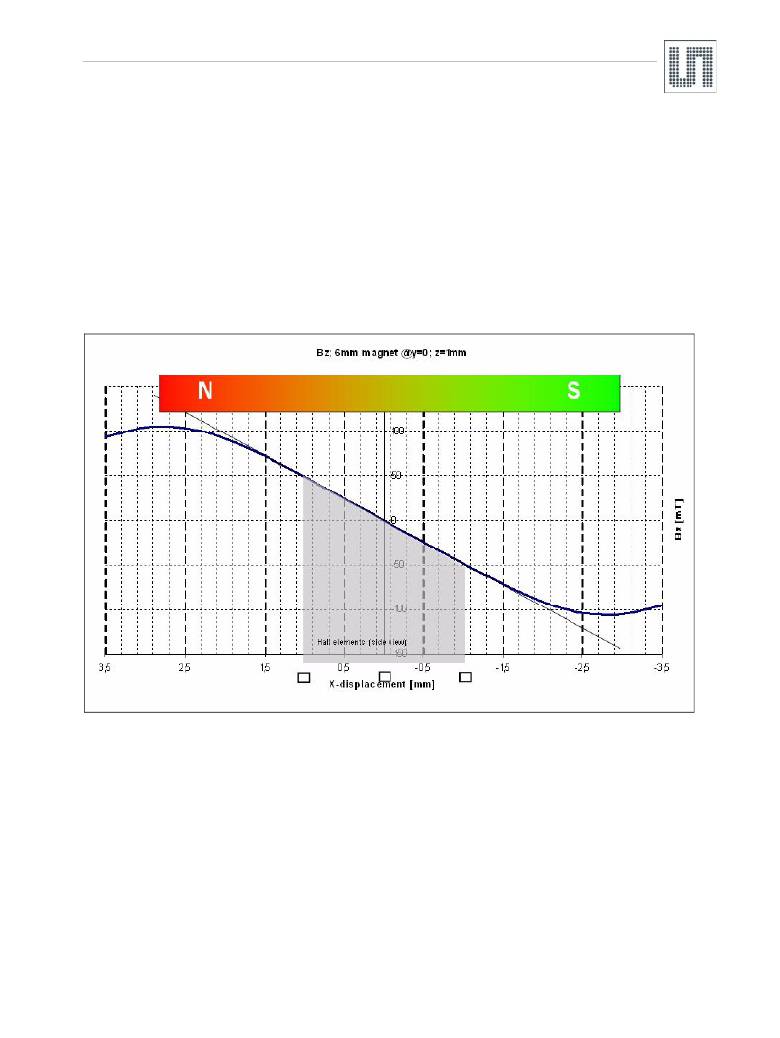
�Figure� 32.� Bz� Field� Distribution� Along� the� X-Axis� of� a� 6mm?� Diametric� Magnetized� Magnet�
�Figure� 32� shows� a� cross� sectional� view� of� the� vertical� magnetic� field� component� Bz� between� the� north� and� south� pole� of� a� 6mm� diameter�
�magnet,� measured� at� a� vertical� distance� of� 1mm.� The� poles� of� the� magnet� (maximum� level)� are� about� 2.8mm� from� the� magnet� center,� which� is�
�almost� at� the� outer� magnet� edges.� The� magnetic� field� reaches� a� peak� amplitude� of� ~±� 106mT� at� the� poles.�
�The� Hall� elements� are� located� at� a� radius� of� 1mm� (indicated� as� squares� at� the� bottom� of� the� graph).� Due� to� the� side� view,� the� two� Hall� elements�
�at� the� Y-axis� are� overlapping� at� X� =� 0mm,� therefore� only� 3� Hall� elements� are� shown.�
�At� 1mm� radius,� the� peak� amplitude� is� ~±� 46mT,� respectively� a� differential� amplitude� of� 92mT.�
�The� vertical� magnetic� field� B� z� follows� a� fairly� linear� pattern� up� to� about� 1.5mm� radius.� Consequently,� even� if� the� magnet� is� not� perfectly� centered,�
�the� differential� amplitude� will� be� the� same� as� for� a� centered� magnet.�
�For� example,� if� the� magnet� is� misaligned� in� X-axis� by� -0.5mm,� the� two� X-Hall� sensors� will� measure� 70mT� (@x� =� -1.5mm)� and�
�-22mt� (@x� =� -0.5mm).� Again,� the� differential� amplitude� is� 92mT.�
�At� larger� displacements� however,� the� B� z� amplitude� becomes� nonlinear,� which� results� in� larger� errors� that� mainly� affect� the� accuracy� of� the�
�system� (see� also� Figure� 34� )�
�www.ams.com/AS5030�
�Revision� 2.4�
�37� -� 44�
�发布紧急采购,3分钟左右您将得到回复。
相关PDF资料
AS5048-DB-1.0
BOARD DEMO AS5048
AS5215 DB
BOARD DEMO AS5215
AS5245 DB
BOARD DEMO AS5245
AS5304-DK-1.0
BOARD DEMO AS5304
AS5311 DB
BOARD EVAL FOR AS5311
ASEK712ELC-05B-T-DK
BOARD EVAL FOR ASEK712ELC-05B
ASPF240D3R
RELAY SSR 3A 240VAC SIP PHASE
ASX220A06
RELAY TELECOM DPDT 10MA 6V
相关代理商/技术参数
AS5030_07
制造商:AMSCO 制造商全称:austriamicrosystems AG 功能描述:8-Bit Programmable High Speed Magnetic Rotary Encoder
AS5030_1
制造商:AMSCO 制造商全称:austriamicrosystems AG 功能描述:8 BIT PROGRAMMABLE HIGH SPEED MAGNETIC ROTARY ENCODER
AS5030-AB
功能描述:插座和适配器 AS5030 Adapter Board RoHS:否 制造商:Silicon Labs 产品:Adapter 用于:EM35x
AS5030ATST
制造商:ams 功能描述:T&R / TSSOP 16
AS5030-ATST
功能描述:板机接口霍耳效应/磁性传感器 RoHS:否 制造商:Honeywell 类型:Bipolar Hall-Effect Digital Position Sensor 工作电源电压:3 V to 24 V 电源电流:3.5 mA 最大输出电流:20 mA 工作点最小值/最大值:5 G, 55 G 最小/最大释放点(Brp):- 55 G, - 5 G 最大工作温度:+ 150 C 安装风格:SMD/SMT 封装 / 箱体:SOT-23
AS5030ATSU
制造商:AMS 功能描述:IC MAGNETIC ROTARY ENCODER 8BIT 16-TSSO 制造商:AMS 功能描述:IC, MAGNETIC ROTARY ENCODER 8BIT 16-TSSO 制造商:AMS 功能描述:IC, MAGNETIC ROTARY ENCODER 8BIT 16-TSSOP; IC Function:Encoder IC; Brief Features:360 Contactless Angular Position Encoding, Two Digital 8-bit Absolute Output; Supply Voltage Min:4.5V; Supply Voltage Max:5.5V; No. of Pins:16 ;RoHS Compliant: Yes
AS5030-ATSU
功能描述:板机接口霍耳效应/磁性传感器 RoHS:否 制造商:Honeywell 类型:Bipolar Hall-Effect Digital Position Sensor 工作电源电压:3 V to 24 V 电源电流:3.5 mA 最大输出电流:20 mA 工作点最小值/最大值:5 G, 55 G 最小/最大释放点(Brp):- 55 G, - 5 G 最大工作温度:+ 150 C 安装风格:SMD/SMT 封装 / 箱体:SOT-23
AS5030-DB
功能描述:磁传感器开发工具 AS5030 Demo Board RoHS:否 制造商:Maxim Integrated 工具用于评估: 接口类型: 工作电压: